


LS1 CAMARO & T/A
| Turbo System Installation Instructions | |
| Step 1: Disconnect battery.
|
|
| Step 2: Remove air box from throttle body to the air filter.
|
|
| Step 3: Cover and save M.A.F.
|
|
| Step 4: Remove all 4 O2 sensors.
|
|
| Step 5: Remove y pipe from cats, to connection at the center of the car.
|
|
| Step 6: Remove cats and save passenger gasket.
|
|
| Step 7: Remove plugs & wires from driver’s side and save.
|
|
| Step 8: Remove air tube from drivers manifold and save.
|
|
| Step 9: Remove all plastic ducting from in front of radiator.
|
|
| Step 10: Remove hood latch and hood latch brackets – save.
|
|
| Step 11: Remove washer bottle and save motor for reinstall.
|
|
| Step 12: Remove lower plastic panels in front of front tires along with the air dam.
|
|
| Step 13: Remove cruise control and mounting bracket.
|
|
| Step 14: Re-install box forward and outside of the frame rails. 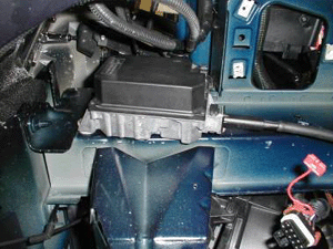 |
|
| Step 15: Use factory plate on rear and drill 4 screws supplied, on front.
|
|
| Step 16: Remove belt from engine. Leave A/C belt on.
|
|
| Step 17: Remove alternator from car. Also remove all alternator brackets from the engine.
|
|
| Step 18: Remove plastic cover from back of the alternator and cut the rear extension off. 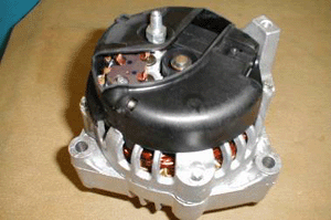 |
|
| Step 19: Reinstall cover back on the back of the alternator.
|
|
| Step 20: Remove power steering hoses from pump to the rack.
|
|
| Step 21: Remove power steering hoses from pump to the rack.
|
|
| Step 22: Remove EGR valve and tubes from pass. side manifold to the top of the intake manifold.
|
|
| Step 23: You will need to modify the EGR mounting bracket by cutting the mounting ear. 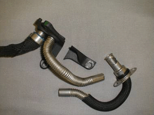 |
|
| Step 24: You also need to strip the heat wrap from the middle of the upper tube to reveal non-flexible portion. Cut in the middle and debur. As shown above.
|
|
| Step 25: Remove electric air pump from left front corner of the car.
|
|
| Step 26: Remove hose from pump to air filter cover.
|
|
| Step 27: Remove mounting bracket from pump and cut as shown in the next photo. Drill 5/16 hole, 5/8 of an inch from the end. 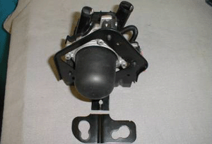 |
|
| Step 28: Reinstall pump onto bracket on the opposite side.
|
|
| Step 29: Remove 10mm bolt and install pump with hoses pointing down. 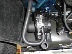 |
|
| Step 30: Use the hose removed earlier to connect pump to the hose sticking out of the fender well.
|
|
| Step 31: Plug in the pump. 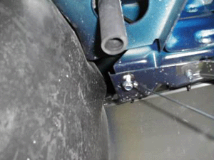 |
|
| Step 32: Remove spark plugs from the passenger side. Regap to .040.
|
|
| Step 33: Locate alternator bracket and 3” support bar, along with (2) 10mm x 1” bolts. Install alternator relocation bracket onto passenger head using (2) 10mm bolts and washers, along with the factory tensioner. 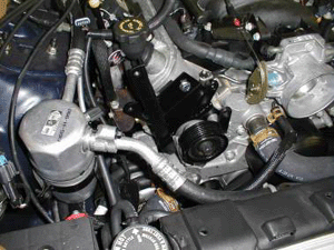 |
|
| Step 34: Remove breather hose from the throttle body to the passenger side valve cover. 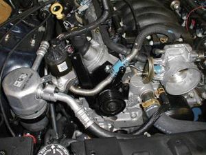 |
|
| Step 35: Install EGR tubes. Some bending of the tubes is required. Mount to alternator bracket with 3/8 x 1” bolt and washer.
|
|
| Step 36: Route EGR tube as shown in photo and clamp together with 3/4 x 2 1/2 “ hose w/ (2) clamps. Do not over tighten, as this will crush the tubes! Install EGR valve onto the mounting plate, tighten, and plug in.
|
|
| Step 37: Install alternator using (2) 3/8 x 3” bolts w/ washers. Install new belt provided. 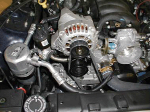 |
|
| Step 38: The wires for the alternator will have to be redone. The 10 gauge positive wire will work. You will have to remove it from the conduit and it will reach the back of the alternator. The small wire will have to be extended using the 4’ red extension wire and (20 butt connectors.
|
|
| Step 39: Locate the cruise control wires. You will need to cut the conduit from the plug, all the way to the main harness. Reroute over the frame rail and through the hole in the fender well. Plug in.
|
|
| Step 40: Remove the oil block above the oil filter and drill a 5/16 hole. Tap with 1/8 pipe. Install # 4 90° fitting pointing back. Install hose being sure that it will clear the transfer case. Run the hose up behind the motor and over the valve cover. 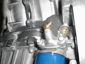 |
|
| Step 41: For the oil drain, mark the pan towards the top and drill 1/4 “ pilot hole and then a 37/64 hole. Use a shop vac to keep shavings from into the pan. Tap 3/8 pipe and install 3/8 x 5/8 90° hose fitting. 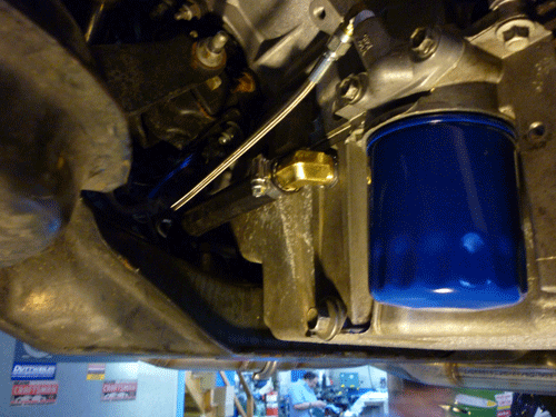 |
|
| Step 42: Install sway bar spacers using (2) spacers and (4) 10mm x 2 ½” bolts. 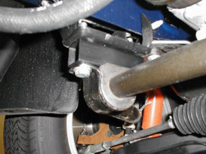 |
|
| Step 43: Install turbo exhaust manifold from the front above the sway bar. Install on to head using factory gasket and bolts. 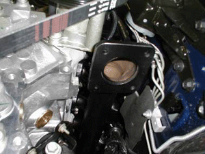 |
|
| Step 44: Install spark plugs and wires, regapping to .040.
|
|
| Step 45: Install air tube onto turbo manifold and hook up to factory hose at the back of the drivers valve cover.
|
|
| Step 46: Locate turbo and remove the exhaust housing. Bolt exhaust discharge onto turbo housing using gasket and (4) 3/8 x 1” bolts. 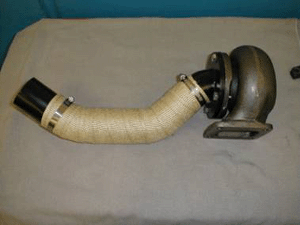 |
|
| Step 47: Install heat wrap onto pipe. Install housing and pipe onto the turbo manifold, using gasket and (4) 3/8 x 1 1/4 “ bolts and locknuts. Install 1/8 x #4 fitting onto turbo. Be sure to use liquid Teflon on threads.
|
|
| Step 48: Install turbo into exhaust housing with the oil drain facing down. Tighten bolts and then install the heat shield using safety wire.
|
|
| Step 49: Install oil drain flange onto turbo using 90° 5/8 fitting, drain plate, gasket, and 92) 8mm bolts. Install oil drain hose with (2) #10 clamps and tighten.
|
|
| Step 50: locate (4) cross over pipes. The one with the wastegate flange bolts onto turbo manifold using (3) 3/8 x 1” bolts and gasket. Install this pipe now and tighten.
|
|
| Step 51: You will need to heat wrap the (2) cross over pipes that mount over the steering rack. 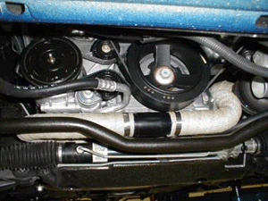 |
|
| Step 52: Install driver side pipe first. Then the passenger pipe. Be sure pipe does not come in contact with positive battery cable. Install pass manifold pipe (h) onto manifold. Position pipes to clear the rack and A/C. Tighten bolts and exhaust clamps on crossover.
|
|
| Step 53: Install pre cat pipe using (3) 3/8 x 1 ¼” bolts and lock nuts. Leave loose for positioning. Install wastegate using (2) gaskets and (4) 5/16 x 1” bolts. Once bolts are started, tighten them all. 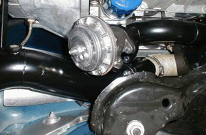 |
|
| Step 54: Install converter and (2) rear exhaust pipes using the factory hanger at the rear of the transmission with (2) 3/8 x 3/4 “ bolts and locknuts, (2) 3” exhaust clamps, (1) band clamp. Position pipes so converter clears the floor and the pipes are not rubbing on anything. Tighten all exhaust parts.
|
|
| Step 55: Install (4) O2 sensors. (1) in the crossover and (1) in the downpipe. (2) go after the converter. All the wires should reach. The (1) in the downpipe will have to be rerouted over the top, but will reach.
|
|
| Step 56: Install oil pressure line onto the turbo and tighten.
|
|
| Step 57: Mount new washer tank on rear of front bumper using (2) #10 screws provided. Remove motor from the factory bottle and install hose provided from the tank to the motor and plug in. 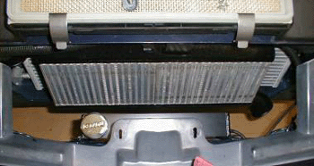 |
|
| Step 58: Install intercooler using 10mm x 1’ bolt and washer and ¼ x 1” bolt and nut with (2) washers. The mounting points are in the middle of the core support. No drilling is needed. 10mm is on the top and the ¼ is on the bottom. 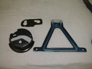 |
|
| Step 59: Modify the hood latch support bracket and reinstall in car. Some adapting may be needed to clear intercooler. 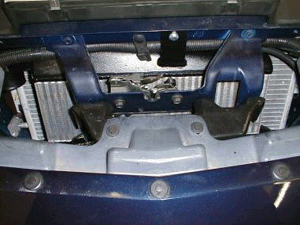 |
|
| Step 60: Locate 2” hot side intercooler pipes and (2) 2” and (1) 2 ½” hose couplers. Install 2 ½” hose on the intercooler and the (1) 2” hose on the turbo. Install pipe with 2 ½” end onto the intercooler and around the core support. Install remaining 2” hose on end of pipe. Install remaining 2” pipe from the turbo to the coupler. Position pipes so that they don’t rub on anything and then tighten all clamps. 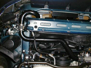 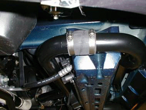 |
|
| Step 61: Locate new power steering hose with (3) fittings. Install (2) fittings into rack, and (1) fitting into steering pump. Route hoses away from belts and other moving parts. Be sure hi-pressure hose goes to the bottom fitting on the rack. Refill pump w/ fluid. 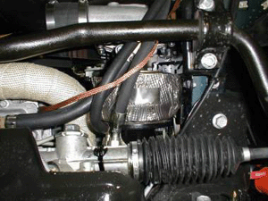 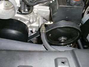 |
|
| Step 62: Install compressor by-pass 2 ½” hose onto intercooler. Locate CPB valve and (2) 6mm Allen bolts along with 2 ½ lower cool pipe w/ mounting flange. Install CPB valve onto pipe with outlet pointing towards the long end of the pipe. 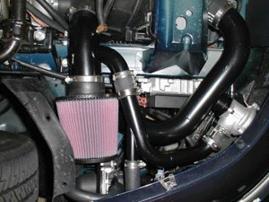 |
|
| Step 63: Install 90° end of pipe onto intercooler and the other end through the hole in the inner fender well. Locate the remaining 2 ½” hose and install onto pipe previously installed. Locate 2 ½ “ to 3 ½” pipe and install into lower pipe. Also install the air temp sensor.
|
|
| Step 64: Locate 90° 3 ½” to 4” elbow and 3 ½” x 2 ¼” hose along with the MAF meter.
|
|
| Step 65: Install 3 ½” hose onto 3 ½” pipe. Install MAF meter onto hose. Be sure flow is in the right direction. Install 3 ½ to 4” rubber elbow onto MAF and throttle body. Position all piping from intercooler to throttle body being sure nothing is rubbing. Tighten all clamps and plug in MAF and temp sensor. 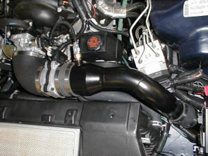 |
|
| Step 66: Locate 2 ¾” rubber elbow, by-pass tube, air intake pipe, air filter, and (2) 1 ½” hoses.
|
|
| Step 67: Install 2 ¾” elbow onto the turbo, with the long end towards the turbo @ about the 4:00 position. Remove upper sway bar mounting bolt and install air intake pipe into 2 ¾” elbow. Re-install bolt through the bracket and tighten bolt and elbow clamps.  |
|
| Step 68: Install air filter.
|
|
| Step 69: Install 1 ½” hoses, with (1) on CBP valve. The other on the air intake pipe. Install by-pass tube. Be sure and tighten all clamps.
|
|
| Step 70: Locate ¼ x 3/8” 90° fitting and 4’ of 3/8 breather hose.  |
|
| Step 71: Install ¼ x 3/8” 90° fitting into air intake pipe at the 9:00 position . Install 3/8 hose from 3/8 fitting to passenger valve cover. Route away from fan belt.
|
|
| Step 72: You will need to find a vacuum source for the CBP valve. The only place is at the heater box before the check valve on the passenger inner fender well. Install tee and run hose to CBP valve. Hook to port on top of CBP.
|
|
| Step 73: Locate (2) 1/8 x 5/32 90° fittings, along with 4’ of vacuum hose.
|
|
| Step 74: Install one fitting in the turbo cover and the other in the wastegate port marked boost. Run hose between turbo and the wastegate, being sure not to contact the exhaust. If using VBC follow instructions in the kit.
|
|
| Step 75: Locate front L&R lower panels. You will have to modify them to clear the air intake pipe and intercooler pipe. 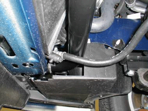 |
|
| Step 76: Install front panels and front air dam. 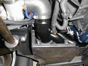 |