1986-1993 Ford Mustang
| Turbo System Installation Instructions | |
| Step 1: On a hard level surface; jack the vehicle up from the front, then the rear and place on jackstands so that car is stable. The front suspension will need to be loaded by placing those stands as far outward on the control arms as possible. This will correctly position front sway bar for installation of the intercooler. Drain coolant and oil from vehicle. 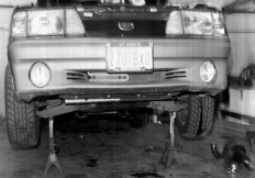 |
|
| Step 2: Disconnect negative battery cable, then positive cable. Remove battery by unbolting hold down wedge from tray, then remove tray from the vehicle by unbolting the 2 bolts in bottom of tray and 1 connecting to inner fenderwell. This tray will later be installed on passenger side. 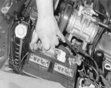 |
|
| Step 3: Exhaust now needs to be unbolted at front of mufflers and at collectors on headers, air injection tube is also to be removed during this step. Reinstall upon completion of installation. |
|
| Step 4: Remove ignition wires from spark plugs, then remove plugs, set these aside and continue. 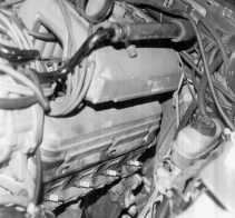 |
|
| Step 5: Remove all hoses from passenger side header area, air pump and control values at rear connection. Hoses will be modified upon reinstallation 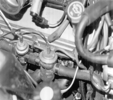 |
|
| Step 6: Remove air box assembly, fresh air ducting into box, and M.A.F. sensor 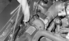 |
|
| Step 7: Remove drivers side header and gasket. Be sure no gasket material is left on exhaust port surfaces, use a gasket scraper to insure a positive seal with supplied header. |
|
| Step 8: Remove oil sending unit and oil filter, these are side by side at front on drivers side of engine block. |
|
| Step 9: Locate the position for oil drain pan fitting now. Clean and mark a spot on the oil pan 2″ below oil filter and 1 1/2″ forward from center of oil filter. Your drain plate can now be centered on that mark and the location of the 3 retaining screws can be marked as well. Center punch your marks to keep drill from wandering. Use a heavy type grease on the tip of drill bits to retain drilling chips and shavings. Be very careful not to let chips go into oil pan. Drill the oil pan drain fitting hole 9/16″, and the retaining screw holes 3/32″. Now apply a liberal amount of silicone sealer to the back side of the drain plate, making sure that NO sealer interferes with the drain passage. Do not overly tighten retaining screws, allow adequate time for sealer to dry, then finish tighten screws. 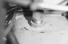 |
|
| Step 10: Take 1/4″ NPT male run tee and separate 1/4″ x #4 fitting from tee. Apply teflon tape or paste to male threads of tee and install at 11:00 position onto existing log which sender was originally mounted to. Teflon sealer should now be applied to male fitting on original sender and 1/4″ NPT x #4 fitting. Sender will attach on tee facing outward, with #4 adaptor in remaining location. 20″ x #4 hose can now be routed upward and later connected to turbo. 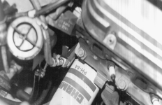 |
|
| Step 11: To clear the turbocharger compressor housing, the power steering pump must be modified. Drain the pump and place a rag as far down as possible in the filler neck. The filler neck will be shortened 2″ by cutting with a hacksaw, 1″ down from the top of the neck. Cut again 2″ lower from previous cut. Use supplied green stripe hose, 2 1/2″ x 2 1/4″ ID, to reconnect cap and original 1″ neck lip to the pump body. Cover pump rotors by 1″ of PS fluid. 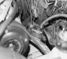 |
|
| Step 12: Once again, be sure that exhaust port surface is completely cleaned of old gasket material. Install stainless turbo with supplied gaskets and 12 pt bolts, tightening evenly. Replace middle lower valve cover bolt with 1/4″ x 3/4″ bolt provided. Install spark plugs, see Step 29 for more about spark plugs and route the spark plug wires with regards to the extra heat the turbo puts out. Install the turbo with the exhaust to the rear, but do not tighten assembly until final hookup. 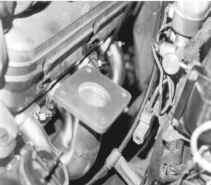 |
|
| Step 13: Install the crossover pipe with supplied 3/8″ x 1″ bolts, washers, and nuts. Do not tighten this assembly until exhaust final hookup is completed. Attach oxygen sensor on passenger side crossover pipe. 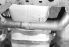 |
|
| Step 14: Install the discharge pipe, bolting the flange to turbo with (3) 3/8″ x 3/4″ bolts and (1) 3/8″ x 1 1/4″ which goes at the 10:30 position (from the rear) to mount the heat shield, do not tighten completely.
|
|
| Step 15: Slip the secondary exhaust Y pipe into the discharge pipe and connect wastegate to crossover pipe, but not tightened completely. 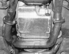 |
|
| Step 16: Final hookup with factory H pipe on floor. Measure 14″ forward of center of air pump discharge tube (located in front of catalytic convertors) on left side, and 11″ forward of center on the right side. These cuts should be made with a hacksaw or portable bandsaw, so that the cuts are straight and clean. Now install collector adaptors and rotate them to hook up with the Y pipe flanges. With the entire exhaust system in position, EVENLY tighten all bolts completely.
|
|
| Step 17: Install new oil filter and oil (20-50 turbo approved oil recommended). Be sure the 30″ x 5/8″ LOR hose for oil drain is connected from the pan fitting to the oil fitting at the bottom of the turbo.
|
|
| Step 18: INTERCOOLER: First remove plastic air director from underneath front of car. Using same hardware, mount front intercooler bracket (has 2 tabs with 5/16″ threads) at same location from which air director was removed. Now install right side (longer of 2) with intercooler mounting holes forward and line up rear hole with tab on outside front corner of crossmember. Mark spot and center punch drilling location, repeat this step for left side. Drill both holes to 11/32″. Bolt front and rear of right bracket loosely in place, place intercooler up onto top of bracket. Bolt intercooler to brackets right and left. Now bolt rear of left side to crossmember and finish tighten assembly.
|
|
| Step 19: Take turbo pressure outlet pipe and install HKS compressor bypass valve with gasket and 6mm x 20 bolts. Install pressure outlet pipe with 2 1/2″ x 2″ ID hose and 2 #36 clamps, this will connect to intercooler with 2 1/2 x 2 1/2 high pressure hose and 2 #40 clamps.
|
|
| Step 20: Connect cool side elbow to intercooler, loosely slip cool side up pipe onto elbow connecting them with 2 1/2″ x 2 1/4″ ID hose and 2 #36 clamps. Connect pressure bonnet with fogger nozzle to cool side up pipe with remaining 2 1/2″ x 2 1/4″ hose and #36 clamps, now attach pressure bonnet to throttle body with 3″ x 2″ hose and 2 #40 clamps.
|
|
| Step 21: Install battery box on right side wheelwell using original nut plates and supplied hardware. Route supplied 5’4″ battery cable around front of radiator and up to battery solenoid. On some 1989-90 cars, new holes must be drilled. Use selftapping screws to attach battery tray to fenderwell. 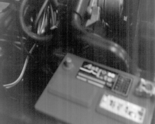 |
|
| Step 22: Locate M.A.F. wire and plug, cut plug from harness 6-10 inches back, splice supplied harness to M.A.F. wires. Soldering the connections and heat shrink wrapping them is the best method. Use crimp solderless connectors only if you feel confident about them. 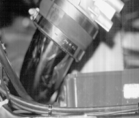 |
|
| Step 23: Air inlet assembly. Install 2 3/4″ x 1 1/2″ adaptor hose on turbo with 3″ x 2″ hose over adaptor and a #48 clamp. Now 3″ elbow with compressor bypass. Leg will attach to 3″ x 2″ hose and #48 clamp. M.A.F. sensor or 3″ x 4″ pipe (for speed density) will be installed between elbow and fresh air intake elbow. Determine the location where 3″ fresh air intake elbow will need to pass through wheelwell. 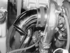 Mark center of hole and drill with 3 1/8″ hole saw. Split a piece of 5/32 vacuum hose to line the edge of your cut to eliminate any vibration noise. Install elbow (fresh air intake ) and air cleaner assembly and support with 3″ x 2″ hose, #48 clamp 1/8″ selftapping screw. Place 1″ x 3″ hose and #48 clamp on the 3″ fresh air elbow on the bottom side of 3/8″ hose fitting. Attach vent hose from oil filler tube on valve cover to fresh air elbow fitting after air cleaner assembly is secure. Inner plastic liner underneath car will need to be trimmed back to clear, use razor knife for this. 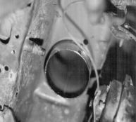 |
|
| Step 24: Fuel pressure regulator installation. Look where injector rail is connected to tank return line (rubber hose) on frame. This is located on passenger side at front of motor. Remove hose from fuel return line (DO NOT USE line with fuel fitting). Connect hose from fuel rail to SIDE fitting on regulator. Connect BOTTOM fitting to tank return line on frame. Vacuum nipple will see boost pressure and the regulator will increase fuel pressure at the injectors at the rate of 9 lbs of fuel pressure for each lb of boost at the regulator.
|
|
| Step 25: Dip stick tube will need to be bent as shown in photo. Use sealer at the base where it enters the block, and attach supplied bracket to header bolt to support upper end of tube. 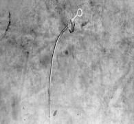 |
|
| Step 26: Reconnect air pump tubes, exhaust tubes and separate all preformed rubber hoses between 2 valves at rear of engine and air injection pump. Modify these hoses as follows: the original hose that connected forward valve to air pump will be reinstalled in a reverse position, the forward end will now need to be 1″ to 1 1/2′ shorter. From rear valves there will be a 3″ straight hose on top and a 3″ hose with a 90 upward bend to attach to the upper valve. Connect the two valves with a 2 1/2″ section of straight hose with original hose at front, reversed and 1″ to 1 1/2″ shorter on new leading end. These should now connect to air pump discharge. Reattach vacuum lines, making the air pump functional once again.
|
|
| Step 27: Ignition and timing. If factory ignition is retained spark plug gap is .030 and timing is -4 BTDC. Follow factory timing adjustment procedures, which are located in engine compartment of vehicle. If MSD6 & Turbo Timing Master ignition is installed the spark plug gap is . 035 and the timing needs to be reset to -10 BTDC, which will give approx. -28 of total timing @ 2500 RPM. 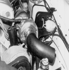 |
|
| Step 28: CHECK LIST: these items must be rechecked to assure proper settings and levels are obtained.
|


